顯示具有 nrf24l01 標籤的文章。 顯示所有文章

2018年12月6日 星期四

Use STM8 to Control nRF24L01


※The complete code is available in here.

In my previous post, I used nRF24LE1, which is an 8051 microcontroller(MCU) integrated nRF24L01 function, to operate Enhanced Shockburst™ (ESB) transceiving. If your MCU would tackle only some simple tack with wireless function, nRF24LE1 is a good selection. However, in some case, nRF24LE1 may be not a choice. For example, nRF24LE1 computing power is limited and does not support CAN bus, pins of nRF24LE1 would be conflicted for your application, multi-channels ADC/I2C/SPI are required,  or just existing product must not be totally reforged..etc. Hence, In here, I would to show how to use STM8L to manipulate nRF24L01.

The STM8L I use here is STM8L101F3P3 features its low price (STM8L10X series is lowest product line of STM8 series.). Because the STM101F1  flash size is not adequate to containing the firmware operating nRF24L01, I use the chip postfix being -F3 rather than -F1.


 To detail explain how to deal with the porting, I start from my another post code of folder nRF24LE1, which has been completely implemented ESB send and receive functions.

 
 零.
    Download ST Visual develop IDESTM8 Cosmic compiler, and  STM8L10x standard peripheral library. you need to provide your email to STMicroelectronics. Then install the STM8 Cosmic Compiler Crack to break through the 32KB limitation.

Set ST Visual develop using the cosmic  compiler : Tools → Option :


一. Download my the code for nRF24LE1 :

Download the code from here, you should extract those :
esb_app.c
esb_app.h
hal\nordic_common.h
hal\nrf24l01p\hal_nrf.c
hal\nrf24l01p\hal_nrf.h
hal\nrf24l01p\hal_nrf_reg.h
hal\nrf24le1\hal_nrf_hw.c
hal\nrf24le1\hal_nrf_hw.h

compiler\c51\stdin.h


And create a folder to contain those code, the folder structure is :

esb_app.c
esb_app.h
nRF24L01_hal\nordic_common.h
nRF24L01_hal\nrf24l01p\hal_nrf.c
nRF24L01_hal\nrf24l01p\hal_nrf.h
nRF24L01_hal\nrf24l01p\hal_nrf_reg.h
nRF24L01_hal\stm8L10x\stdin.h
nRF24L01_hal\stm8L10x\hal_nrf_hw.c
nRF24L01_hal\stm8L10x\hal_nrf_hw.h


二 .  Modify the necessary code:
The firmware architecture diagram is as below, The blocks framed purple is the code you need to modify/implement.


esb_app.h :
export esb_irq function :


:

void esb_receiving_event_has_been_handled(void);


/*nRF24L01 IRQ*/
#if !defined(NRF24LE1_H_) && !defined(NRF24LU1P_H)
void esb_irq(void);
#endif

esb_app.c :

comment out the line to set register RFCKEN and RF, and remove the keyword "static"  of function esb_irq.

void esb_init(void)
:
#if defined(NRF24LE1_H_) || defined(NRF24LU1P_H)
 RFCKEN = 1;  //enable RF timer
#endif
:
#if defined(NRF24LE1_H_) || defined(NRF24LU1P_H)
 RF = 1; //enable rf interrupt
#endif
:
}/*enhanced_shockburst_init*/

:

/*static */ void esb_irq(void)
{
:


As the diagram shows, the hal_nrf,c and  hal_nrf.h  would be intact, but  hal_nrf_hw.c and hal_nrf_hw.h need to be completely implemented. Is is because the SPI operations are high MCU-dependency, and pin definition is high board-dependency.

The schematic of my board is :


keypoints:

PC0 pin is for nRF24L01 IRQ.
PB4 pin is for nRF24L01 CSN.
PB3 pin is for nRF24L01 CE.

In this manner,  hal_nrf_hw.h as :


#ifndef HAL_NRF_STM8L101XX_H__
#define HAL_NRF_STM8L101XX_H__
#include "STM8l10x_conf.h"

#define data     
#define pdata
#define xdata

/** Macro that set radio's CSN line LOW.
 *
 */
#define CSN_LOW() do {  GPIO_ResetBits( GPIOB, GPIO_Pin_4);} while(false)
/** Macro that set radio's CSN line HIGH.
 *
 */
#define CSN_HIGH() do { GPIO_SetBits( GPIOB, GPIO_Pin_4);} while(false)

/** Macro that set radio's CE line LOW.
 *
 */
#define CE_LOW() do {GPIO_ResetBits(GPIOB, GPIO_Pin_3);} while(false)

/** Macro that set radio's CE line HIGH.
 *
 */
#define CE_HIGH() do {GPIO_SetBits(GPIOB, GPIO_Pin_3);} while(false)

/** Macro for writing the radio SPI data register.
 *
 */
#define HAL_NRF_HW_SPI_WRITE(d) do{\
                 while (SPI_GetFlagStatus(SPI_FLAG_TXE) == RESET);\
                 SPI_SendData(d);\
                } while(false)

/** Macro for reading the radio SPI data register.
 *
 */
#define HAL_NRF_HW_SPI_READ()  SPI_ReceiveData()
  
/** Macro specifyng the radio SPI busy flag.
 *
 */
#define HAL_NRF_HW_SPI_BUSY   (RESET == SPI_GetFlagStatus(SPI_FLAG_RXNE))

/**
 * Pulses the CE to nRF24L01 for at least 10 us
 */

#define CE_PULSE() do { \
  uint8_t count; \
  count = 20; \
  CE_HIGH();  \
  while(count--){} \
  CE_LOW();  \
  } while(false)

 
#endif // HAL_NRF_STM8L101XX_H__

/** @} */


Those lines to define data, pdata and xdata are for avoiding compilation error.

hal_nrf_hw.c:


#include <stdint.h>
#include "hal_nrf.h"
#include "STM8l10x_conf.h"

uint8_t hal_nrf_rw(uint8_t value)
{
 while (RESET == SPI_GetFlagStatus(SPI_FLAG_TXE));
 SPI_SendData(value);
 
 //wait for receiving a byte
 while(RESET == SPI_GetFlagStatus(SPI_FLAG_RXNE));
 return SPI_ReceiveData();
}


三. Create the project.

  Create a workspace of ST Visual Develop with what the chip you use, and create a project inside it. the project folder in this structure:


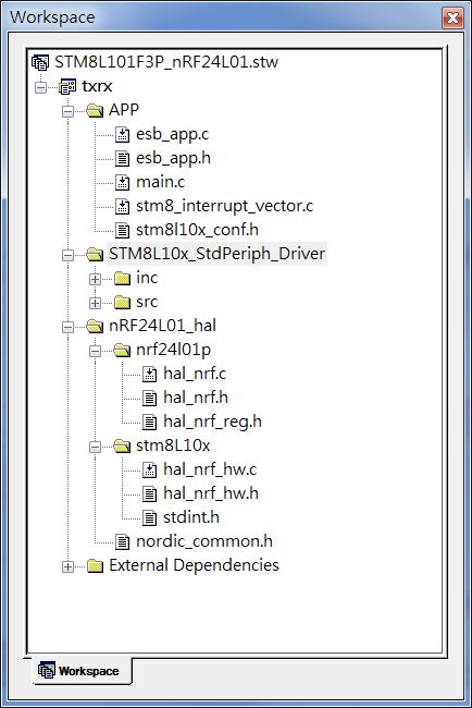
stm8_interrupt_vector.c and stm8l10x_conf.h are auto-generated files. The  STM8L10x_StdPeriph_Driver folder contains the driver files of of STM8L10x standard peripheral library, in directory STM8L10x_StdPeriph_Lib\Libraries\STM8L10x_StdPeriph_Driver, for inc and src folder respectively.


The next stuff I need to do,  is to complete the nRF24L01 initialization. Pay attention :: it is not ESB initializtion function, which has been implemented in esb_app.c. The nRF24L01 initialization is for initializing the interface resources used in communicated with nRF24L01.

There are two part: initialize the Serial Peripheral Interface Bus(SPI), and the General-purpose input/output(GPIO).

The pins:

PB7 pin is SPI_MISO, input, high = 1.
PB6 pin is SPI_MOSI, output, high = 1.
PB5 pin is SPI_SCK, output, high = 1.

PB4 pin is for nRF24L01 CSN. output, set = 1.
PB3 pin is for nRF24L01 CE, output, set =1.

PC0 pin is for nRF24L01 IRQ, input,  external interrupt, active-low.

According to above definition, the the data sheet of nRF24L01 for SPI timing explanation(CPOL= low, CPHA = rising edge, more detail explanation about CPOL and CPHA you could refer to here) , the code for nRF24L01 initialization is :


void spi_init(void)
{
 //Config the GPIOs for SPI bus
 
 /*
  GPIOB::GPIO_Pin_7  -> SPI_MISO   
  GPIOB::GPIO_Pin_6  -> SPI_MOSI  
  GPIOB::GPIO_Pin_5  -> SPI_SCK   
 */
 GPIO_Init( GPIOB, GPIO_Pin_7, GPIO_Mode_In_PU_No_IT);
 GPIO_Init( GPIOB, GPIO_Pin_5 | GPIO_Pin_6, 
  GPIO_Mode_Out_PP_High_Slow);
  
 SPI_DeInit();
 //enable clock for SPI bus
 CLK_PeripheralClockConfig(CLK_Peripheral_SPI, ENABLE);

/*SPI BAUDRATE should not be over 5MHz*/
#define SPI_BAUDRATEPRESCALER   (SPI_BaudRatePrescaler_4)

 //Set the priority of the SPI
 SPI_Init( SPI_FirstBit_MSB, SPI_BAUDRATEPRESCALER,
            SPI_Mode_Master, SPI_CPOL_Low, SPI_CPHA_1Edge,
            SPI_Direction_2Lines_FullDuplex, SPI_NSS_Soft);
 //Enable SPi
 SPI_Cmd(ENABLE); 
 
}/*spi_init*/


void nrf24l01_init(void)
{  
 spi_init();
 
 /*GPIOB::GPIO_Pin_4 -> SPI::NSS -> NRF24l01::CSN*/
 GPIO_Init( GPIOB, GPIO_Pin_4, GPIO_Mode_Out_PP_High_Fast);
 
 /*GPIOB::GPIO_Pin_3 -> NRF24l01::CE*/
 GPIO_Init( GPIOB, GPIO_Pin_3, GPIO_Mode_Out_PP_High_Fast);

 /*GPIOC::GPIO_Pin_0 -> NRF24l01::IRQ*/ 
 GPIO_Init(GPIOC, GPIO_Pin_0, GPIO_Mode_In_PU_IT); 
 EXTI_SetPinSensitivity(GPIO_Pin_0, EXTI_Trigger_Falling_Low);
 EXTI_ClearITPendingBit(GPIO_Pin_0);
}/*spi_init*/


The last stuff to do is to register an external interrupt function for nRF24L01's IRQ in file stm8_interrupt_vector.c.

 In my board, pin PC0 is the pin for nRF24L01 IRQ.  According to the STM8L101xx datasheet( in section "interrupt vector mapping", p.32), the PX0 interrupt number is 8.

Therefore, add the interrupt function in stm8_interrupt_vector.c :

struct interrupt_vector const _vectab[] = {
 {0x82, (interrupt_handler_t)_stext},
:
:
 {0x82, NonHandledInterrupt}, /* irq6  */
 {0x82, NonHandledInterrupt}, /* irq7  */
 
 {0x82, external_interrupt0_handler}, /* irq8  */
 
 {0x82, NonHandledInterrupt}, /* irq9  */


The interrupt function definition is:

@far @interrupt void external_interrupt0_handler(void)
{
 EXTI_ClearITPendingBit(GPIO_Pin_0); 
 esb_irq();
}/*external_interrupt0_handler*/

This very clear that once the interrupt is triggered, function esb_irq, which is as the same as nRF24LE1's, will be called to deal with the callback events of send/receive/max re-try.


It is all.


below is the uart output of this STM8L101F3PU + nRF24L01 while this device is communicating with nRF24LE (the original one, before this porting).


If I turn off the nRF24LE1, the uart output is :


It is compatible with the previous works totoally. Of course, this porting is able to communicate with my previous work on nRF5X.

2018年11月27日 星期二

nRF51/nRF52 Runs BLE Peripheral and ESB Protocol Concurrently


   The code for this post is here.   

  Continue my previous post about Nordic's Enhanced Shockburst™(ESB)  reliable transceiving, In this post I would like to discuss how to combine ESB with Bluetooth low energy(BLE).

       BLE protocol is widely adopted on the consumer mobile devices, ALL mainstream mobile operation systems support that, and ALL device have been implemented the function. If is extremely easy to find out a device supporting BLE at hand. The BLE network topology is point to point, it is very straightforward and intuitive. For the simplest topology, the connection setting is quick and instinct, easy to be accepted by dummy consumer. Thus, lots mobile peripherals use this protocol connecting with mobile to transfer data or fetch command.
     In most case, one to one structure is enough for the personal device, lots  sporting wrist/belt products have existed in the market.
     However, in home or small commercial cases, one to one structure is not enough, even enough, it is only adequate. You could try to consider a user scenario :  there is a large busking,  several installation separated in an performance stage, ,the performer needs to interactive those device. The controller needs to use phone or computer to ignite fire, spray gas.. etc. Besides, It is better for the stuffs that they could use phone to control those devices, because their working space is limited.

     WIFI is a solution for the small performance issue, but WIFI might be not a good solution, It is because the setting of WIFI is troublesome, and once the phone connect to a router which is not on internet, the phone is not able to access internet either (even the phone's LTE function running).

     ESB protocol provides star and mesh  topology, but the phones do not support ESB.  However, nRF51/nRF52chip is able to  run the two protocols at the same time, that fills the gap to use phone controlling or receiving data from multi-devices.

   In this demonstration, there is a nRF51/nRF52 device conveying BLE data to ESB and vice versa. For demonstrating the transfer in detail,  I also provide a device based on nRF24LE1 for sending/receiving ESB packets.

 
※ My code is based on nRF5X SDK 11, you could download that from here.

   零. Download the code from Github.
Place the whole folder under nRF5X_SDK11_ROOT\examples\ble_peripheral. The project files are as the same as SDK default examples, in pca10028 (nRF51) and pca10040 (nRF52) repectively. All projects are for Keil-C 5.
       nRF24LE1 device code is in under folder nRF24LE1, in this folder,  all required files have been included, you do not need to download nRFgo SDK.
        UART are in baudrate 38400 in all device.

 一. About the nRF5x code : 

   The main.c is based on ble_app_template, macro _INTACT denotes where I modified. I added:

    UART function for print output.
    A timer, to print time series per second.
    A BLE service, providing to send/receive data  to/from BLE central (phone).

 
   The code under esb and esb_timeslot folder I downloaded from here. notice that the code in esb folder is not the same as SDK default containing (nRF5X_SDK11_ROOT\components\properitary_rf\esb), the adopted IRQs have been changed. And the esb_timeslot\esb_timeslot.c and esb_timeslot\esb_timeslot.h have been modified for my application.

   Due to the IRQs collision might bring the ESB function hanging. Hance, as this thread mentioned, about line 467, esb_timeslot\esb_timeslot.c should be modified:


void nrf_esb_event_handler(nrf_esb_evt_t const * p_event)
{
    :
    :
    if (p_event->evt_id & NRF_ESB_EVENT_RX_RECEIVED)
    {
#if !defined(_INTACT)   
    fetch_esb_rx_data();
#else   
        /* Data reception is handled in a lower priority interrup. */
        /* Call UESB_RX_HANDLE_IRQHandler later. */
        NVIC_SetPendingIRQ(UESB_RX_HANDLE_IRQn);
#endif   
    }
}


The nrf_esb_event_handler function is called by function ESB_EVT_IRQHandler (esb/esb.c, line 909), which is a software IRQ. But UESB_RX_HANDLE_IRQn is the re-used of WDT_IRQ.  It is not appropriate to manipulate the other IRQ inside a non-software IRQ. Thus, it is necessary to modify the code for directly fetching ESB data  in the function nrf_esb_event_handler.


 二. The code nRF24LE1 :
  The code is copied from folder txrx of my previous post's repository. Note that function, about 100 of file esb_app.c :
 

hal_nrf_enable_dynamic_ack(false);

It should be consisted with  nRF5X code esb_timeslot/esb_timeslot.c, about line 523:


nrf_esb_config.selective_auto_ack = false;

If you set that as false in nRF24LE1 but leave that as true in nRF51 the UART output of nRF24LE1  would display rf_max_retry_count_reached  but the packet indeed delivered.  Disable dynamic_ack/auto_ack means you need to manually sendback ack packet(zero length packet) to sender.

  Result :

  In BLE scanner,  the peripheral name shows as "NRF51 ESB to/from ":
※ the device name in code has been changed as "ESB to/from BLE" for the original name was "NRF51 ESB to/from BLE", which is too long to display completely(over 20 bytes). But below images were captured before the fixing .


After the phone connected with the nRF5x and set notification(subscribing). the values would be received periodically and vary with time.


I sent a data as to the nRF5x:


And the nRF24LE1 would received this data, as its UART showing:


Reference :

Make Nordic Enhanced ShockBurst™ (ESB) Transceivers as Multiceiver and Reliable

Migration from µESB to nrf_esb

Running micro-ESB concurrently with BLE


2018年11月16日 星期五

Make Nordic Enhanced ShockBurst™ (ESB) Transceivers as Multiceiver and Reliable


    ※ This post focuses on nRF24LE1, if you are interested in how to use an independent microcontroller to control NRF24L01, please refer to my another post.

    ※ The multi-sending and multi-receiving code is here,  Receiver send back Acknowledge code is here.

      Nordic's Enhanced ShockBurst™ transceivers have been very widely adopted in IoT (Internet of things) industries or maker area, they feature affordable prices while being of mass deployment. Also the design references, documents, demonstration and example code are huge, tt is easy for users to use the transceivers and chips adapting their purposes.
      There are enormous example code of operating these transceivers, those code are on Arduno, STM32, MSP430...and so forth. In the most circumstances, the are ample for the users.
     But those code are few in mentioning "How to implement a RELIABLE multi-transmission". Even about the issue "how to operate a sender with designating a receiver",  the explanation is obscure. The lots discussion are written in words, the example code is lacked.
      The reliable transmission issue for are very essential for IoT purpose :  if the transmission is not reliable, it is difficult to plan a network topology.  If the mechanism of checking reliability does not be done in network-link layer, the mechanism must be implemented in application. It leads it is difficult to design such protocol, and the code be tedious.
      It is important also for the designated destination issue. If in network link layer, the sender is not able to specify which transceiver should receive.It  brings all device would receive the packets of the EACH sender, it results in, the firmware work be increased to filter out redundant data. Besides, if one transceiver receives too much packets simultaneously, it may be hanging.

    This post tries to demonstrate how to designated the receiver, and provide a example of the transmission with acknowledge.

  甲. Implement three firmware, one is able to multi-send with designating destination, another is able to multi-receive with designating source, the other is sender and receiver in one, but sending and receiving are from different address.

 乙. Implement a pair of firmware, the receiver is able to receive packet from six different addresses reliably.

 
   There are three famous Enhanced ShockBurst™ transceivers and chips in the market, I explain ahead:

壹. nRF24L01/nRF24L01+ : Pure transceiver, SPI communication with a microcontroller. (Note: nRF24L01 with plus does not support 250kb data rate)

貳. nRF24LE1  : An 8051 based microcontroller integrated Enhanced ShockBurst™ function, operate the communication via internal SPI.

參. nRF24LU1 : Similar with nRF24LE1, but this microcontroller has been integrated USB device function.

    My codes are based on nRF24LE1, but it is easy to port the code to the other microcontrollers.

一. implement a sender/receiver pair, which support multi-sending/receiving with designated destination and sources.


take look at  trscvr_para.h, those parameters must be the same for the transceivers which are  going to communicate each other. You should regard the ADDR number, those are adopted to set the pipe addresses:

#define ADDR_PIPE0_0        (0x10)
#define ADDR_PIPE0_1        (0x11)
#define ADDR_PIPE0_2        (0x12)
#define ADDR_PIPE0_3        (0x13)
#define ADDR_PIPE0_4        (0x14)


#define ADDR_PIPE1TO5_1        (0xE1)
#define ADDR_PIPE1TO5_2        (0xE2)
#define ADDR_PIPE1TO5_3        (0xE3)
#define ADDR_PIPE1TO5_4        (0xE4)

#define ADDR_PIPE1_0        (0x81)
#define ADDR_PIPE2_0        (0x82)
#define ADDR_PIPE3_0        (0x83)
#define ADDR_PIPE4_0        (0x84)
#define ADDR_PIPE5_0        (0x85)


The address structure for communication pipe, is as below (ref: nRF24L01+ Preliminary Product Specification v1.0, page 36):


PIPE0 ADDR_PIPE0_0 ADDR_PIPE0_1 ADDR_PIPE0_2 ADDR_PIPE0_3 ADDR_PIPE0_4
PIPE1 ADDR_PIPE1_0 ADDR_PIPE1TO5_1 ADDR_PIPE1TO5_2 ADDR_PIPE1TO5_3 ADDR_PIPE1TO5_4
PIPE2 ADDR_PIPE2_0 ADDR_PIPE1TO5_1 ADDR_PIPE1TO5_2 ADDR_PIPE1TO5_3 ADDR_PIPE1TO5_4
PIPE3 ADDR_PIPE3_0 ADDR_PIPE1TO5_1 ADDR_PIPE1TO5_2 ADDR_PIPE1TO5_3 ADDR_PIPE1TO5_4
PIPE4 ADDR_PIPE4_0 ADDR_PIPE1TO5_1 ADDR_PIPE1TO5_2 ADDR_PIPE1TO5_3 ADDR_PIPE1TO5_4
PIPE5 ADDR_PIPE5_0 ADDR_PIPE1TO5_1 ADDR_PIPE1TO5_2 ADDR_PIPE1TO5_3 ADDR_PIPE1TO5_4

Only pipe 0 have complete 5-byte address values ; the first to the fourth bytes of the others are the same, there are only zeroth bytes different.

The addressese should be the same for a pipe of a TX corresponding to a RX to make the communication work. (but the pipe numbers are not necessary to be the same)


The addresses are allocated to each pipe via below code(line 39 of esb_app_ptx_noack.c , line 36 of esb_app_txrx_noack.c and line and line ine 37 of esb_app_prx_noack.c ) :


{
 uint8_t i;
 for(i = HAL_NRF_PIPE0; i <= HAL_NRF_PIPE5; i++)
  hal_nrf_set_address(i, l_pipe_addr[i]);
}/*set all addresss*/


Specify a pipe as TX pipe (line 108 of esb_app_ptx_noack.c and line 128 of esb_app_txrx_noack.c) :
hal_nrf_set_address(HAL_NRF_TX, l_pipe_addr[tx_pipe_number]);


Specify the pipe(s) to receive packets(line 45 of esb_app_prx_noack.c and line 43 of esb_app_txrx_noack.c) :
hal_nrf_open_pipe(RX_PIPE, false); 

Open in here, does not mean "Enable the RF function", it is only to open the receiving function of that pipe; and the false in the argument, means to disable the auto-ack function.
If the pipe is only for sending data, it is not necessary to call the hal_nr_open_pipe function.


In my code, The PTX would send packet via pipe 5, and RX receive packet from pipe 5. UART, in baudrate 38400.

The UART outputs are :


PTX:
rf snd in pipe = 5, len = 6:: 05 da 00 20 eb bc
rf snd in pipe = 5, len = 6:: 05 db 00 20 ed b0
 2158 sec
rf snd in pipe = 5, len = 6:: 05 dc 00 20 ef a4
 2159 sec
rf snd in pipe = 5, len = 6:: 05 dd 00 20 f1 98
rf snd in pipe = 5, len = 6:: 05 de 00 20 f3 8c
 2160 sec
rf snd in pipe = 5, len = 6:: 05 df 00 20 f5 80

PRX:
rf rcv in pipe = 5, len = 6:: 05 be 00 20 b5 0c
rf rcv in pipe = 5, len = 6:: 05 bf 00 20 b7 00
 4645 sec
rf rcv in pipe = 5, len = 6:: 05 c0 00 20 b8 f4
rf rcv in pipe = 5, len = 6:: 05 c1 00 20 ba e8
 4646 sec
rf rcv in pipe = 5, len = 6:: 05 c2 00 20 bc dc

If you modify the RX_PIPE as HAL_NRF_PIPE0 or change the address value, and leave the TX codes intact, the output would be

 8 sec
 9 sec
 10 sec
 11 sec
 12 sec
 13 sec

That is, the PRX receiving nothing. Is is very natural, The pipe addresses of TX and RX  are not corresponding to each other.


If you add a device, which runs the TXRX code, and define the macro _RX_FOR_ALL_CHANNEL in PRX (in line 12 of  PRX\esb_app_prx_noack.h) and leave the PTX in working, the output would be :

TXRX :
rf snd in pipe = 3, len = 6:: 05 6c 00 00 d4 e4
rf rcv in pipe = 5, len = 6:: 05 cc 00 01 90 64
 55 sec
rf snd in pipe = 3, len = 6:: 05 6d 00 00 d6 d8
rf rcv in pipe = 5, len = 6:: 05 cd 00 01 92 58
rf snd in pipe = 3, len = 6:: 05 6e 00 00 d8 cc
rf rcv in pipe = 5, len = 6:: 05 ce 00 01 94 4c
 56 sec
rf snd in pipe = 3, len = 6:: 05 6f 00 00 da c0
rf rcv in pipe = 5, len = 6:: 05 cf 00 01 96 40

PRX:

rf rcv in pipe = 5, len = 6:: 05 4a 00 02 86 7c
rf rcv in pipe = 3, len = 6:: 05 ec 00 01 ce e4
rf rcv in pipe = 5, len = 6:: 05 4b 00 02 88 70
 76 sec
rf rcv in pipe = 3, len = 6:: 05 ed 00 01 d0 d8
rf rcv in pipe = 5, len = 6:: 05 4c 00 02 8a 64
rf rcv in pipe = 3, len = 6:: 05 ee 00 01 d2 cc
 77 sec
rf rcv in pipe = 3, len = 6:: 05 ef 00 01 d4 c0

The TXRX recive packet from pipe 5, and send the packets vis pipe 3. PRX receives the packets from the ALL pipes : the packets of PTX from pipe 5, the packets of TXRX from pipe 3.

     To here, you could try to think for a while for why Nordic calls communication pipe as pipe : it causes  a pipe, does not represent a device, it represents a communication channel of a corresponding sender/receiver.  If your topology needs, a pipe could be used for a group of sender/receiver (it is a bit like the "group" term in Zigbee).


二.  Make a sender/receiver pair, the communication in which is reliable : there sender would know if the receiver is indeed received the packet or not.


The key to enable auto-acknowledge mechanism, is to set the corresponding address as HAL_NRF_TX and HAL_NRF_PIPE0, and open the two pipe with auto-ack function(about line 46 of PTX/esb_app_ptx_ack.c).


 {
  uint8_t i;
  for(i = HAL_NRF_PIPE0; i <= HAL_NRF_PIPE5; i++)
   hal_nrf_set_address(i, l_pipe_addr[i]);
 }/*set all addresss*/

#ifndef _TX_FOR_ALL_CHANNEL  
 hal_nrf_set_address(HAL_NRF_PIPE0, l_pipe_addr[TX_PIPE]); 
 hal_nrf_set_address(HAL_NRF_TX, l_pipe_addr[TX_PIPE]);
 
 hal_nrf_open_pipe(HAL_NRF_PIPE0, true);
 hal_nrf_open_pipe(TX_PIPE, true);
#endif

it is necessary to open the pipe 0 is for receiving ack signal .


If you would like to append some data to the acknowledge packet from receiver side, you must call the 2 function (about line 65 of PTX/esb_app_ptx_ack.c) :

 hal_nrf_enable_dynamic_ack(true);
 hal_nrf_enable_ack_payload(true);

In sender's RF interrupt request (RF-IRQ) function, you could determine if it is ack-appending or not though which pipe receives. The determination I adopted in my code  about line 131 of PTX/esb_app_ptx_ack.c. Pay attention: the ack packets are from pipe 0 always :


if(irq_flags & (1<<HAL_NRF_RX_DR))
{ 
 //ack payload received
 uint8_t received_pipe; 
 if(false == hal_nrf_rx_fifo_empty())
 {
  uint16_t pipe_and_len;
  pipe_and_len = hal_nrf_read_rx_payload(&l_rx_payload[0]);
  
  received_pipe = (uint8_t)(pipe_and_len >> 8);
  l_rx_payload_len = (uint8_t)(0xff & pipe_and_len);
 }/*if */
 
 hal_nrf_flush_rx();
 if(HAL_NRF_PIPE0 == received_pipe)
  l_is_ack_reached_flag = 1;
  
}/*if */


The judgment is very important while you want to implement a device of sender/receiver as one (as the TXRX folder) .


In the receiver side, the ack-packet will be sendbacked via the function:

void hal_nrf_write_ack_payload(uint8_t pipe, const uint8_t *tx_pload, uint8_t length);

the pipe in argument must be as the same as the receiving pipe. You could refer to function esb_send_ack_data, in PRX/esb_app_prx_ack.c, line 147.


After preliminary explanation, I show their UART output for more detail clarification:

PTX :


rf snd in pipe = 3, len = 6:: 05 38 04 12 15 00
ack received ::  6a 6a 6a 6a
 2205 sec
rf snd in pipe = 3, len = 6:: 05 39 04 12 15 00
ack received ::  6b 6b 6b 6b
rf snd in pipe = 3, len = 6:: 05 3a 04 12 15 00
ack received ::  6c 6c 6c 6c
 2206 sec
rf snd in pipe = 3, len = 6:: 05 3b 04 12 15 00
ack received ::  6d 6d 6d 6d

PRX:

rf rcv in pipe = 3, len = 6:: 05 37 04 12 15 7d
ack len = 4::  6a 6a 6a 6a
 3000 sec
rf rcv in pipe = 3, len = 6:: 05 38 04 12 15 7d
ack len = 4::  6b 6b 6b 6b
rf rcv in pipe = 3, len = 6:: 05 39 04 12 15 7d
ack len = 4::  6c 6c 6c 6c
 3001 sec
rf rcv in pipe = 3, len = 6:: 05 3a 04 12 15 7d
ack len = 4::  6d 6d 6d 6d

The PTX and PRX are consisted with each other. PTX sends a serial number  to PRX, PRX acknowledges with another series of number.

If you turn off the PRX device, PTX would show the warning of retry_count_reached. It is, HAL_NRF_MAX_RT IRQ  has been triggered (about line 105 of PTX/esb_app_ptx_ack.c) :  The retry count has been reached but the packet does not been sent successfully yet.


 2986 sec
rf snd in pipe = 3, len = 6:: 05 53 04 12 15 00
rf_max_retry_count_reached!!
rf snd in pipe = 3, len = 6:: 05 54 04 12 15 00
rf_max_retry_count_reached!!
 2987 sec
rf snd in pipe = 3, len = 6:: 05 55 04 12 15 00
rf_max_retry_count_reached!!


But if HAL_NRF_PIPE0  do not be open with auto_ack (hal_nrf_open_pipe(HAL_NRF_PIPE0, true) ), this HAL_NRF_MAX_RT IRQ would never been triggered even the max-retry count has been reached.

Max retry count and trying-interval are able to be set via the function:


void hal_nrf_set_auto_retr(uint8_t retr, uint16_t delay);

I called it at line 7 of PTX/esb_app_tx_ack.c.


     In this example, I assume all sending event request reciever's ack signal. If your sender suddenly does not need the ack from the receiver, you could call the function for sending the packet:

void hal_nrf_write_tx_payload_noack(const uint8_t *tx_pload, uint8_t length);

Calling this function would set the no_ack flag of ESB packet as true. Once the  no_ack flag has been set, The receiver would not sendback the auto-ack signal to sender.
     (The dynamical ack function, hal_nrf_enable_dynamic_ack, must be configured before calling this function, as line65, PTX/esb_app_ptx_ack.c,  More detail about the ESB packet format, please refer to here)

     However, in the application layer, there is NO WAY for the receiver to query if the no_ack flag in received packet has been set or not. If your receiver sendbacks an ack_payload to a sender requesting no_ack,  your sender would not received that.
     A solution to this issue is to adopt different pipe specified for ack/no_ack transmission, which is Nordic's suggestion. The other solution I know, is to give a bit in payload to describe if the packet needs ack-payload or not.


NOTE :

For PTX, you could change macro TX_PIPE to the other pipe, or enable macro _TX_FOR_ALL_CHANNEL for sending each channel by turns. There is also macro PX_PIPE/_PX_FOR_ALL_CHANNEL for PRX, those functions are similar to PTX's.

Nordic's doc said the Constant ESB_MAX_ACK_PAYLOAD_LEN, is 32 bytes, but based on my test, the length is 4 bytes only. If you know how to effectively sendback a packet of 32 bytes appended with acknowledge, please tell me. But from my experience, 4 bytes is very enough for appending to acknowledge in a good IoT architecture.